Update 12/03/2011: I set up my OpenWrt VM using VMWare Player because I couldn’t get USB to work in VirtualBox. See What’s Wrong With VrtualBox for descriptions of my problems. And please let me know if you have solutions.
ClearOS will not have built-in Wi-Fi support until the next version, 6.1, is released. This blog entry is for those who want to add wireless coverage to their current ClearOS boxes. I will go over the steps to create an OpenWrt virtual machine using VMWare Player, and to configure it as an wireless access point.
Network Configuration
ClearOS is a Linux server/gateway distribution. Since it currently lacks Wi-Fi support, often an external wireless AP is added to a network to provide Wi-Fi coverage. That was my setup until a couple of weeks ago, when my wireless router failed. Its replacement is a virtual network with a virtual wireless AP. This tables compares the old, real network with the new, virtual network.
| Function | Real network | Virtual network |
| DHCP server | ClearOS | ClearOS |
| Wi-Fi Access Point | Netgear wireless router. Its DHCP function was disabled. | VMWare virtual machine running OpenWrt. OpenWrt’s DHCP function is also disabled |
| Connection from ClearOS to Wi-Fi | eth2, a Fast Ethernet adapter. It was connected directly to a LAN port on the wireless router. |
vmnet2, VMWare virtual network adapter #2. vmnet2 and the OpenWrt VM are connected through VMWare’s virtual switch |
| Connection from Wi-Fi to ClearOS | Netgear router LAN port #1. Connected to eth2 through a cable. |
VM eth0, a virtual Fast Ethernet adapter. It is configured as an OpenWrt LAN port. |
| Wi-Fi radio | Router radio | VM wlan0, a USB wifi adapter. It is configured as a LAN interface. OpenWrt connects eth0 and wlan0 using a Linux network bridge. |
The two networks have similar topology because I wanted to replicate the real network in a virtual environment.
Selecting a USB Wireless Adapter
There are two requirements when selecting an adapter for an OpenWrt access point: The adapter must support access point mode (most newer ones do), and its driver is distributed with OpenWrt (many are). To check if these conditions are met, start by finding the name of the adapter’s driver on Linux wireless wiki. Its USB device page lists more than 350 adapters and their drivers. After finding the driver, look for its features on the driver page. The adapter can function as an access point if “Yes” appears in the “AP” column.
To determine whether the driver is distributed with OpenWrt, look for its kernel module package in the package list. The name of the package is usually “kmod-<driver name>” but sometimes slightly different. For example, on Linux wireless wiki there are drivers “ath9k_htc” and “rt2800usb”, but the OpenWrt package names are “kmod-ath9k-htc” and “kmod-rt2800-usb”, respectively. For this reason it is best to search for a partial name (“kmod-ath” or “kmod-rt28”) and review the result. The package lists are available from OpenWrt.
Let’s take Rosewill RNX-EasyN1 as an example. It does not appear on Linux wireless wiki, but searching on Google I learned it is built around Ralink RT3070 and needs driver rt2800usb. On Linux wireless wiki driver page, I learned the adapter does work in AP mode. Looking through the package list of OpenWrt 10.03.1-rc6, I found its driver package “kmod-rt2800-usb”.
Finally, beware that newer adapters may not work with older drivers. For example, Rosewill RNX-EasyN1 does not work with the rt2800usb driver distributed with OpenWrt 10.03.
Installing and Configuring VMWare Player
I chose VMWare Player for virtualization because it works and it is free. Xen and KVM aren’t supported by ClearOS 5.2, which is what I use. VirtualBox has problem with USB pass-through.
VMWare Player can be downloaded from from VMWare’s web site. Registration is required to download. Look for “VMWare Player for 32-bit Linux” and “VMWare VIX API for 32-bit Linux” on the download page. As of 11/30/2011, 4.0.1 is the latest version, and the files are “VMware-Player-4.0.1-528992.i386.bundle” and “VMware-VIX-1.11.1-528992.i386.bundle”.
Before installing VMWare, gcc and kernel headers need to be installed. VMWare needs them to re-compile its kernel modules.
bash$ if [ `uname -r | grep PAE` ]; then yum install gcc kernel-PAE-devel ; else yum install gcc kernel-devel ; fi
This one liner checks the kernel release and installs the matching kernel headers.
To install VMWare Player
bash$ chmod +x ./VMware-Player-4.0.1-528992.i386.bundle
bash$ ./VMware-Player-4.0.1-528992.i386.bundle --console
Installation will start after accepting the license agreement and answer a few questions.
Similarly, to install VIX API
bash$ chmod +x ./VMware-VIX-1.11.1-528992.i386.bundle
bash$ ./VMware-VIX-1.11.1-528992.i386.bundle --console
By default, VMWare activates only vmnet1 and vmnet8 virtual network adapters on the host. To activate vmnet2, first add the following lines to /etc/vmware/networking.
answer VNET_2_DHCP no
answer VNET_2_HOSTONLY_NETMASK 255.255.255.0
answer VNET_2_HOSTONLY_SUBNET 192.168.75.0
answer VNET_2_VIRTUAL_ADAPTER yes
Altough 192.168.75.0/24 is shown, feel free to select any valid subnet for vmnet2. In fact, vmnet2 will not be assigned an IP address in the final setup.
Now create a device node for vmnet2 and restart VMWare virtual network.
bash$ mknod /dev/vmnet2 c 119 2; vmware-networks --stop; vmware-networks --start
Running ifconfig should show vmnet2 active with IP address 192.168.75.1
Configuring ClearOS
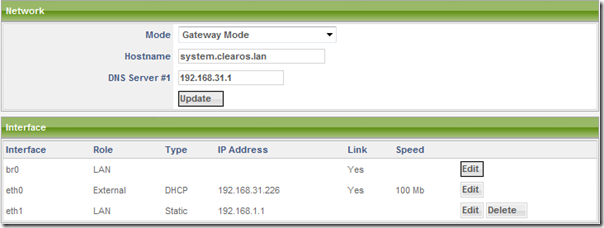
Although vmnet2 is active at this point, ClearOS’s webconfig still can’t detect it. (I do not know the reason. If anyone does, please leave a comment.) This is a problem because webconfig is the best tool for configuring ClearOS. However there is a workaround. Since webconfig can detect Linux Ethernet bridges, adding vmnet2 to a bridge creates a suitable network interface.
The first step is to install the bridge utilities.
bash$ yum install bridge-utils
To set up the Ethernet bridge
bash$ brctl addbr br0
bash$ ifconfig vmnet2 inet 0.0.0.0
bash$ brctl addif br0 vmnet2
bash$ ifconfig br0 up
The first command creates the bridge br0, the second deletes vmnet2’s IP address, the third adds vmnet2 as a port of br0, and finally the last command activates the bridge.
The next step is to use webconfig to configure br0. After logging in, select “IP Settings” under the Network menu, and then click on the “Edit” button for br0.
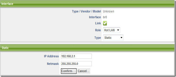
On the next page, assign a role and IP setting to br0. For example here br0 is set up as the “Hot LAN” interface with a static IP address 192.168.2.1. Click on “Confirm” to save changes.
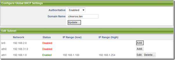
The final step in webconfig is to add DHCP settings for br0. Select “DHCP Server” under the Network menu, and then click on the “Add” button for br0.
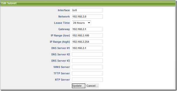
On the next page, make suitable changes for your network and click on “Update” to save the settings. The following image shows the default ClearOS settings for the 192.168.2.0/24 subnet.
Now log out from webconfig and return to a shell session to edit two files. One is /etc/sysconfig/network-scripts/ifcfg-br0. This file is updated whenever the IP settings of br0 change. However ClearOS has a bug and classifies br0 as a regular Ethernet interface instead of a Linux bridge. To fix this problem change the value of TYPE from "Ethernet" to "Bridge", as shown below. Make sure to use a uppercase “B” followed by lowercase “ridge”. This field is case sensitive. Also, the value of <code>HWADDR</code> should be set to <code>00:00:00:00:00:00</code>. A bridge does not have a MAC address until an interface is added.
DEVICE=br0
TYPE="Bridge"
ONBOOT="yes"
USERCTL="no"
HWADDR="00:00:00:00:00:00"
BOOTPROTO="static"
IPADDR="192.168.2.1"
NETMASK="255.255.255.0"
Second, add the following lines to /etc/rc.d/rc.local
ifconfig vmnet2 inet 0.0.0.0
/usr/sbin/brctl addif br0 vmnet2

vmrun -T player \
    start /etc/vmware/guests/OpenWrt-10.03.1-rc6/OpenWrt-10.03.1-rc6.vmx \
    nogui
/etc/rc.d/rc.local is the last init script to run, after all real and virtual network interfaces are configured. The purpose of these three lines is to connect vmnet2 to br0 and to start the OpenWrt virtual machine. The parameter /etc/vmware/guests/OpenWrt-10.03.1-rc6/OpenWrt-10.03.1-rc6.vmx of the last command specifies the VM’s configuration file, which is discussed in the next section.
Setting Up OpenWrt VM
With ClearOS and VMWare configured and ready, it’s time to install the virtual machine. One that boot into OpenWrt 10.03.1-rc6 is available from my SkyDrive. Its files are stored in gzipped tar files. (I will add new VMs when new versions become available.)
The content of a tar file can be extracted to any location. I prefer /etc/vmware/guests.
bash$ mkdir /etc/vmware/guests
bash$ cat OpenWrt-10.03.1-rc6.tar.gz | ( cd /etc/vmware/guests; tar xzvf - )
./OpenWrt-10.03.1-rc6/
./OpenWrt-10.03.1-rc6/OpenWrt-10.03.1-rc6-disk1.vmdk
./OpenWrt-10.03.1-rc6/OpenWrt-10.03.1-rc6.vmx
The .vmdk file is the VM’s disk file. The .vmx file is its configuration file.
For VMWare to automatically connect a USB Wi-Fi adapter to a VM, the adapter’s vendor ID and product ID need to be in the .vmx file. To find them first install Linux USB utilities.
bash$ yum install usbutils
Next use lsusb to list USB devices connected to the host PC. The following result shows the Rosewill adapter and a USB thumb drive.
bash$ lsusb
Bus 007 Device 001: ID 0000:0000
Bus 002 Device 003: ID 125f:0000 A-DATA Technology Co., Ltd.
Bus 002 Device 001: ID 0000:0000
Bus 002 Device 002: ID 148f:3070 Ralink Technology, Corp. RT2870/RT3070 Wireless Adapter
Bus 005 Device 001: ID 0000:0000
Bus 001 Device 001: ID 0000:0000
Bus 003 Device 001: ID 0000:0000
Bus 004 Device 001: ID 0000:0000
Bus 006 Device 001: ID 0000:0000
Bus 008 Device 001: ID 0000:0000
For each device two 4-digit hexadecimal numbers, separated by a colon, appear after “ID”. The number before colon is the vendor ID; the other is the product ID. In this example “148f” is the vendor ID, and “3070” is the product ID.
Now append the following line to the VM’s .vmx file (/etc/vmware/guests/OpenWrt-10.03.1-rc6/OpenWrt-10.03.1-rc6.vmx if the commands shown earlier are followed verbatim):
usb.autoConnect.device0 = "vid:<vendor ID> pid:<product ID>"
Using the Rosewill adapter as an example again:
usb.autoConnect.device0 = "vid:148f pid:3070"
OpenWrt First Boot
At this point the virtual machine is ready for its first boot. To start the VM,
bash$ vmrun -T player start /etc/vmware/guests/OpenWrt-10.03.1-rc6/OpenWrt-10.03.1-rc6.vmx nogui
This is one of the commands added to /etc/rc.d/rc.local.
To confirm the VM is up and running, do a DNS lookup.
bash$ nslookup OpenWrt localhost

Server:         localhost
Address:        127.0.0.1#53

Name:   OpenWrt
Address: 192.168.2.134
To configure OpenWrt, start a telnet session to the returned IP address.
bash$ telnet 192.168.2.134
Trying 192.168.2.134...
Connected to 192.168.2.134.
Escape character is '^]'.
 === IMPORTANT ============================
  Use 'passwd' to set your login password
  this will disable telnet and enable SSH
 ------------------------------------------

BusyBox v1.15.3 (2011-10-29 04:41:06 CEST) built-in shell (ash)
Enter 'help' for a list of built-in commands.

  _______                     ________        __
 |       |.-----.-----.-----.|  |  |  |.----.|  |_
 |   -   ||  _  |  -__|     ||  |  |  ||   _||   _|
 |_______||   __|_____|__|__||________||__|  |____|
          |__| W I R E L E S S   F R E E D O M
 Backfire (10.03.1-RC6, r28680) --------------------
  * 1/3 shot Kahlua    In a shot glass, layer Kahlua
  * 1/3 shot Bailey's  on the bottom, then Bailey's,
  * 1/3 shot Vodka     then Vodka.
 ---------------------------------------------------
root@OpenWrt:/#
As the screen suggests, the first order of business should be setting a secure password.
Next is to install the adapter driver and access point software. As mentioned in “Selecting a USB Wi-Fi adapter”, the Rosewill adapter’s driver package is “kmod-rt2800-usb”:
root@OpenWrt:/# opkg update ; opkg install hostapd kmod-usb2 kmod-rt2800-usb
Substitute “kmod-rt2800-usb” with the appropriate driver for your setup.
Once the driver is installed, use OpenWrt’s wifi command to generate the default wireless configuration file. “uci” commands are then used to set options.
root@OpenWrt:/# wifi detect > /etc/config/wireless
root@OpenWrt:/# uci set wireless.radio0.disabled=0
root@Openwrt:/# uci set wireless.@wifi-iface[0].ssid=<your SSID>
root@OpenWrt:/# uci set wireless.@wifi-iface[0].encryption=psk2
root@OpenWrt:/# uci set wireless.@wifi-iface[0].key=<your passkey>
root@OpenWrt:/# uci commit
Here the first command creates the template; the second enables the radio; the third sets Wi-Fi’s SSID; the fourth and fifth commands enable encryption; and the last command saves configuration changes. By default the wireless network and OpenWrt LAN port eth0 are bridged, so no network options need to change.
Since ClearOS is already set up as the DHCP server for the wireless subnet, OpenWrt’s DHCP server needs to be disabled and stopped.
root@OpenWrt:/# /etc/init.d/dnsmasq disable
root@OpenWrt:/# /etc/init.d/dnsmasq stop
Finally, restart OpenWrt’s network interfaces.
root@OpenWrt:/# /etc/init.d/network restart
Now your ClearOS box with built-in Wi-Fi access point is ready.
What’s Wrong With VirtualBox?
I started this project using VirtualBox 4.1.6 and 4.0, but I just couldn’t get the USB adapters to work. I tried to two adapters. One is TP-Link TL-WN722N (Atheros AR9271), and the other is the Rosewill. When running in VirtualBox, OpenWrt couldn’t download the adapter’s firmware. OpenWrt did initialize the Rosewill adapter and set up the access point, but no device could connect to it. If you know the solutions to these problems, please let me know.
VMWare Has Problems Too
VMWare can’t seem to reset the TP-Link adapter. If I rebooted the OpenWrt VM after the adapter was initialized, OpenWrt wouldn’t be able to access it again. But if I unplugged it and then plugged it back in, everything would be fine. Or if I rebooted ClearOS, it would work too.
Changes on OpenWrt Disk Image
Before converting the raw ext2 disk image to a .vmdk file, I made three changes.
- From GRUB configuration file I deleted all things related to the serial port. There is no need to work through a serial-port console when the VM’s regular console is available. This change shortens boot time.
- The default configuration of
eth0is changed from static IP address to DHCP, reporting the hostname “OpenWrt”. This is necessary because OpenWrt is just a normal device in the network, not a DHCP server or router. - In the network initialization script
/etc/init.d/network, a 10-second delay is added before the wireless interface is brought up, because it takes a while for USB devices to settle down.
History
12/03/2011: Add descriptions of VirtualBox USB problem, VMWare/TP-Link problem, and chanages to OpenWrt disk image.
